The CDOT menu contains several Add On tools for use within the CDOT environment. Beginning with version 3.01, the Add On drop down menu contains picks to unload each Add On tool. Below is shown the v3.02 Add On drop down menu.
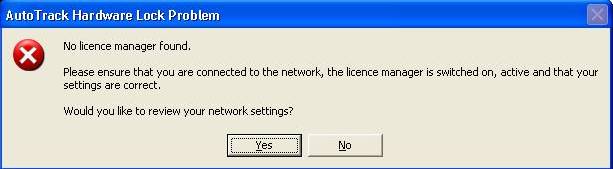
This utility requires that AutoTrack is installed on the local workstation. If the software does not exist or the user is not connected to the network the following error message will appear: MicroStation must be exited and re-opened to clear the error.
The brkline mdl creates a break-line symbol at any point on a given line.

When you launch the brkline utility, you will see the following information.
The following message will be displayed in the command box.
and the following request will be displayed in the key-in box.
Key in the Size defines the space that is created in the line.
This command will launch the barmenu style Bridge Menu.
This tool will search the correct directories to find all .rdl files created using Bentley Redline, and attach them as reference files to the current file.
The CDOT Steel Add-On application consolidates a vast number of bridge/steel cells into one user-friendly application. Cells can be sorted by existing or proposed status, Type, Name, and Fill. An additional option allows graphics to be placed as complex strings/shapes if cells are not the preferred method of placement.
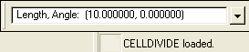
This utility works in the Key-in window of MicroStation. Upon selection of Add On's>Cell Divide Load from the CDOT Menus, the user defines a spacing and angle for an active cell to be placed along an element. It follows the element at a specific spacing and places a cell on that element using the spacing. The angle of the cell is relative to the element itself.
This command is used to create revision clouds for As-Built and Revision purposes. The command will place a primitive cloud or convert a MicroStation placed shape to a cloud.

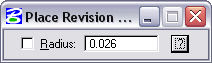
Dialog box showing Primitive cloud placement mode with Radius key-in mode.

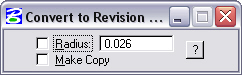
Dialog box showing convert shape to Revision cloud placement mode with Radius key-in mode and copy option.
Currently there is a known problem with editing text that has been placed along an arc. This is particularly problematic with the Survey Cap cells where there is curved text placed along the circle of the cap. When editing using MicroStation Text Editor, the resulting text becomes straight rather than following the curve. This tool allows the user to edit this text and have it remain along the original element.
The gINT Translator allows the user to take data directly from their gINT boring log software and convert this to MicroStation graphics. This application imports gINT bore hole log data and graphs samples (gINT Fence Diagram). The transformations used by gINT Translator are fairly complex as it processes multiple scales, multiple angles, and attempts to keep bar graphs in line with sample points. Users are encouraged to use the Automatic Fit option for graph display.
This tool allows the user to measure between elements, similar to using the MicroStation measure tools, and get an output with both slope and horizontal distance. The tool was created to help negate the confusion when using 3D files at different elevations.
The Launch Misc. Tools button will activate another menu containing several tools created specifically for the CDOT workspace. These include, from the left below, Change Active Symbology ByLevel, Change All Elements to ByLevel Symbology, and Shift Linestyle.

This button will change the active symbology to bylevel symbology in the event that any of the symbology, weight, color, or style, is changed from bylevel.
This will return all elements in the drawing to bylevel symbology. In the event the user has placed elements with non-bylevel symbology, this command will select every element in the drawing and change symbology to bylevel.
The shift linestyle command will shift the gap of a linestyle allowing the user to move a gap or a symbol from a vertex. In the example below the environmental linestyle has placed a symbol at the vertex causing the linestyle to draw incorrectly (left side). After using the Shift Linestyle tool the linestyle now displays correctly (right side).


The ModZ utility will modify the Z elevation of an element in a 3D design file to a specified elevation as determined by the key-in value (as shown below). The utility will modify single graphics, fence graphics, or all graphics within a design file. Caution should be exercised with the Fence and All commands as the command may adversely affect graphics that were not intended to be modified.
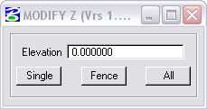
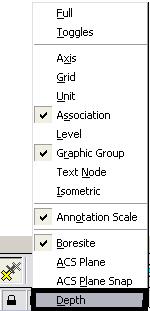
Before running the modz utility, make sure the Depth Lock has been turned off enabling the graphics to be edited.
This utility will convert point cells to graphic cells. The cells must be selected in the file with the selection tool or a fence and the command should be run. The system does not prompt the user, it simply executes the command.
Read more about Point cells and Graphic cells
The Roughen command allows the user to create a rough surface out of a straight line, as shown below. This command was created to allow the Bridge group to show a rough surface where two concrete pours connect.

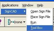
This selection will launch the 3rd party application SignCAD

Stratify Survey creates DGN files for Survey data (codes, elevations, names, notes, and symbols) and moves the corresponding data from the current DGN file to a new DGN file. In addition, the Stratify Survey application attaches the existing contour reference file.
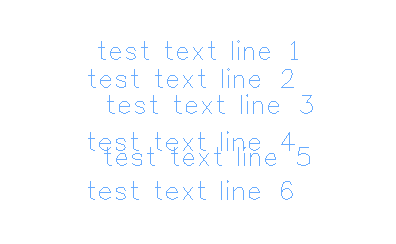
The Text to Node command will take individual pieces of text and combine them into a paragraph for easier editing. The example below shows 6 independent pieces of text.
Selecting the Text to Node pick from the Add-on's
drop down menu will activate a Text to Node Icon. ![]() Once
selected the user is prompted to identify element, then accept/reject
the selection.
Once
selected the user is prompted to identify element, then accept/reject
the selection.

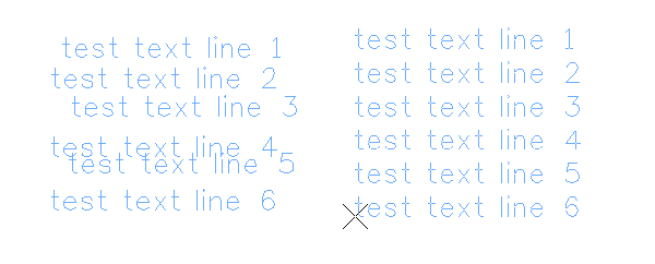
Select each piece of text and then data in view window to select the last piece. The resulting text will be in paragraph form, allow the user to place where desired, and edit the resulting text as a paragraph.
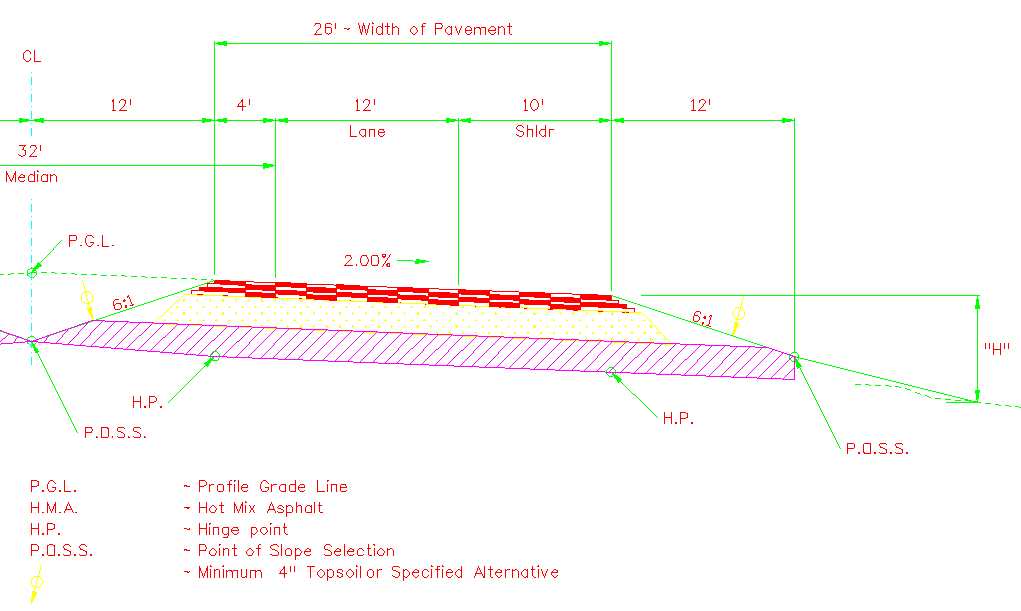
The typical section program automates the process of drawing typical sections. Shown below, the program allows the user to input various information including pavement type and thickness, median type, shoulders, and curbs. Once input, the program will draw the typical section into the MicroStation drawing using editable MicroStation elements. This allows the user to modify the section should they be creating a section not covered by the program.
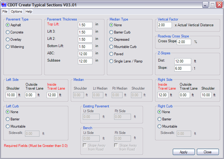
The user must first select the jpcTypicalSection##.dgn located in the Projectes\jpc\Design\Drawings directory. This drawing has the correct annotation scale set to allow the corresponding text to be drawn at the correct scale. An example of 1/2 of a typical section is shown below. Read the attached workflow to find out more.